Introduction
This section of the blog talks about what I learnt about 2D Computer Controlled Machining. I learnt about the process of using a CNC router and how I used it to make a key compoenet for my project.
Competency test
Firstly, I had to take a competency test. This test required us to use the large CNC router located in T11C and create a coaster.
| Steps Taken | Explanation |
|---|---|
|
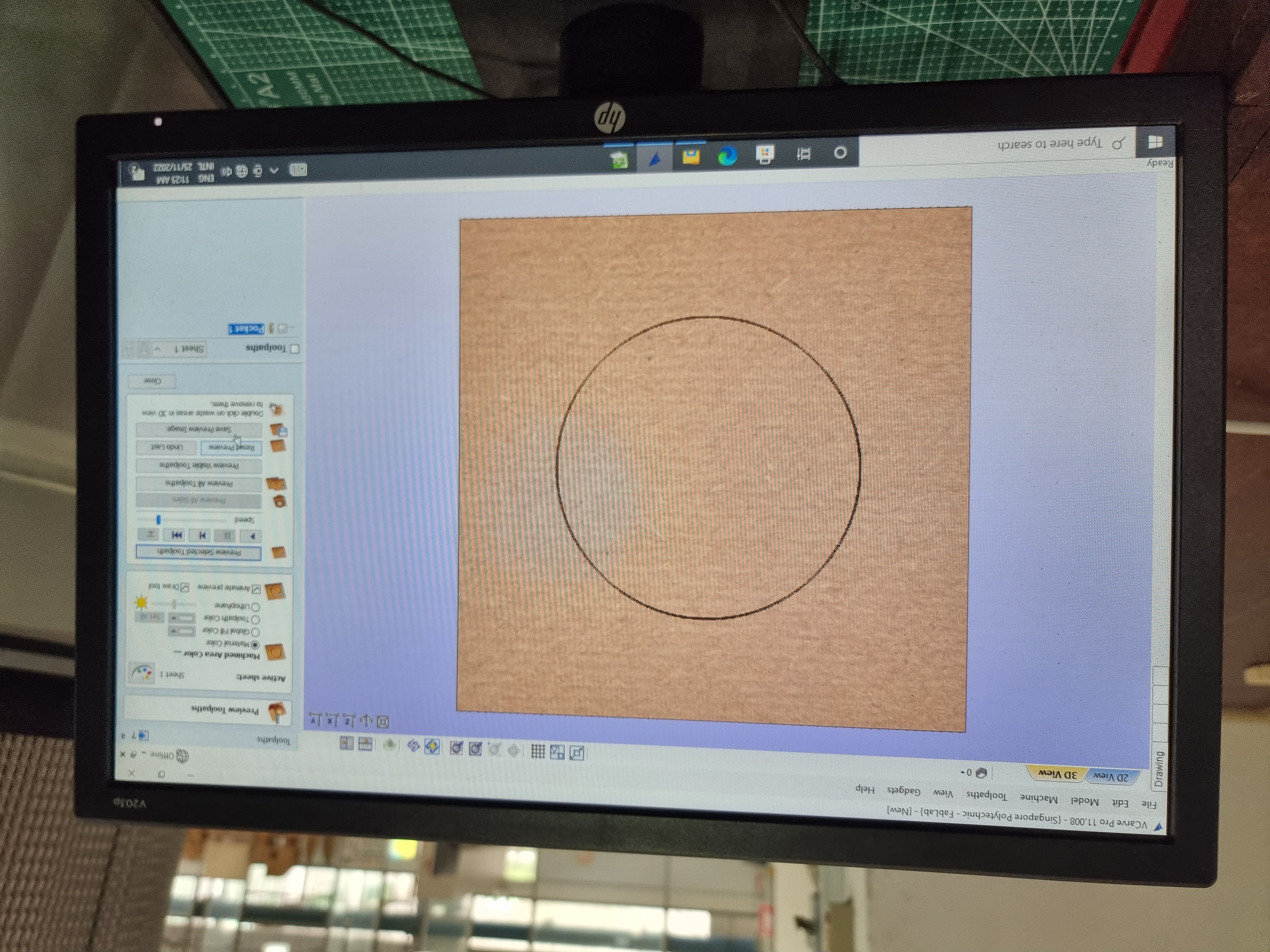
Step 1Open the DXF file containing the model you would want to cut using the router. Depending on what you are planning to cut, select what lines are pockets and what are profiles. If a line is a pocket it means that the cutter would not cut the material all the wat through. While if the line chosen is a profile, the cutter would cut through it. |
|
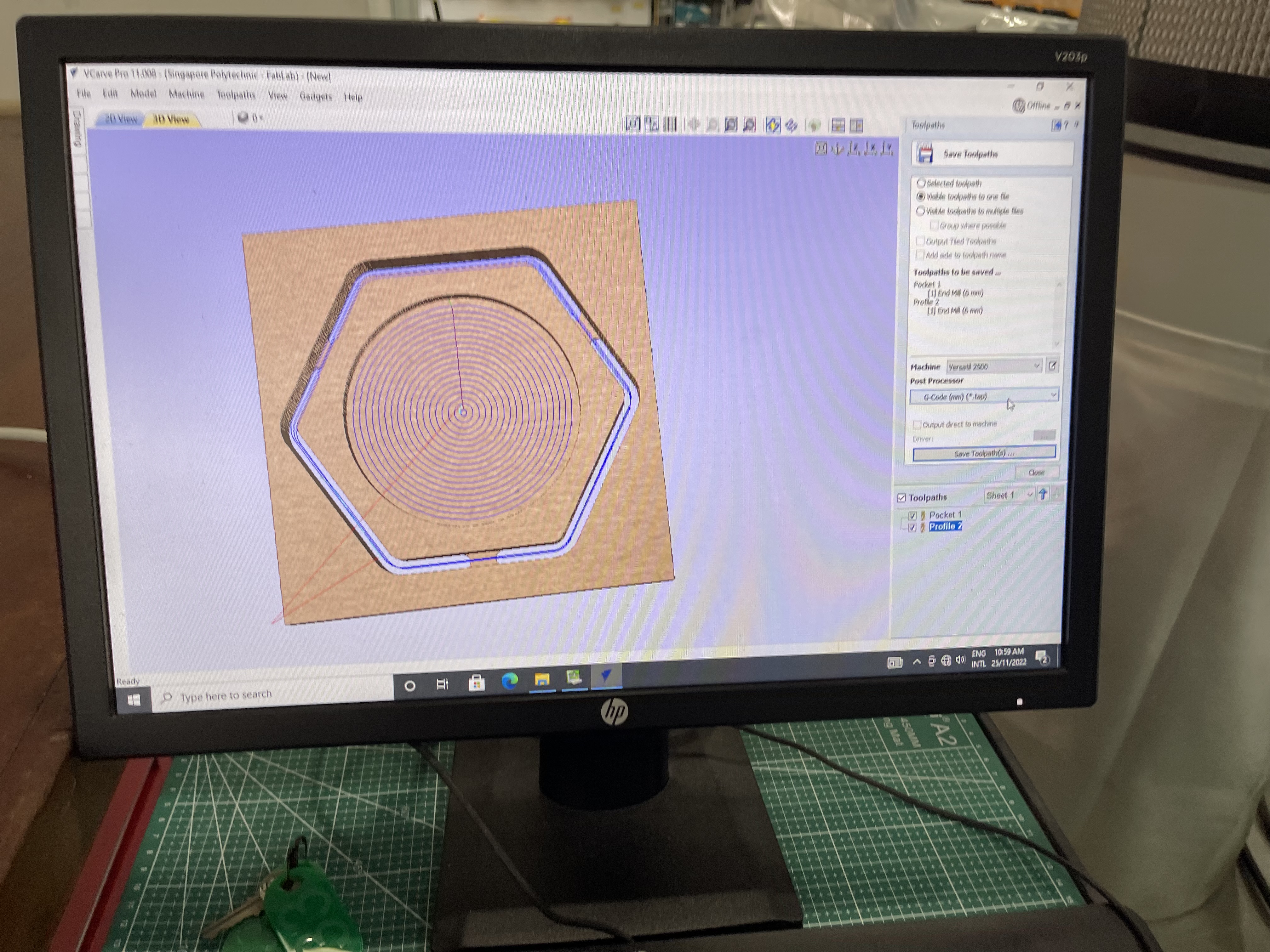
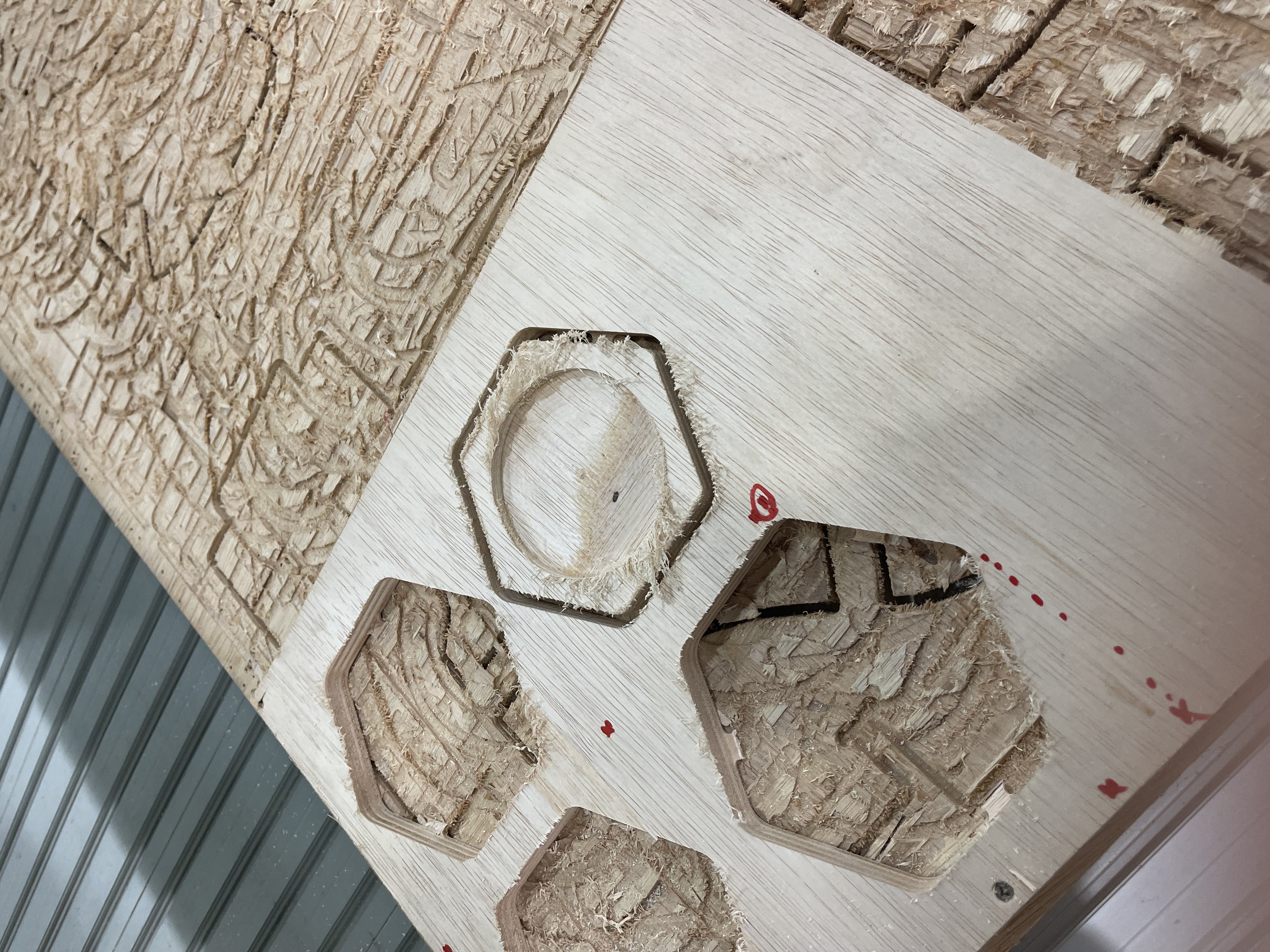
Step 2Shown in the picture on the left, you are able to see the two types of cuts made. The pocket being the one in the centre and the profile being the one on the outside. Additonally, add tabs to the workpiece to ensure that it does not fly out. Save the toothpath and export the G-code. |
|
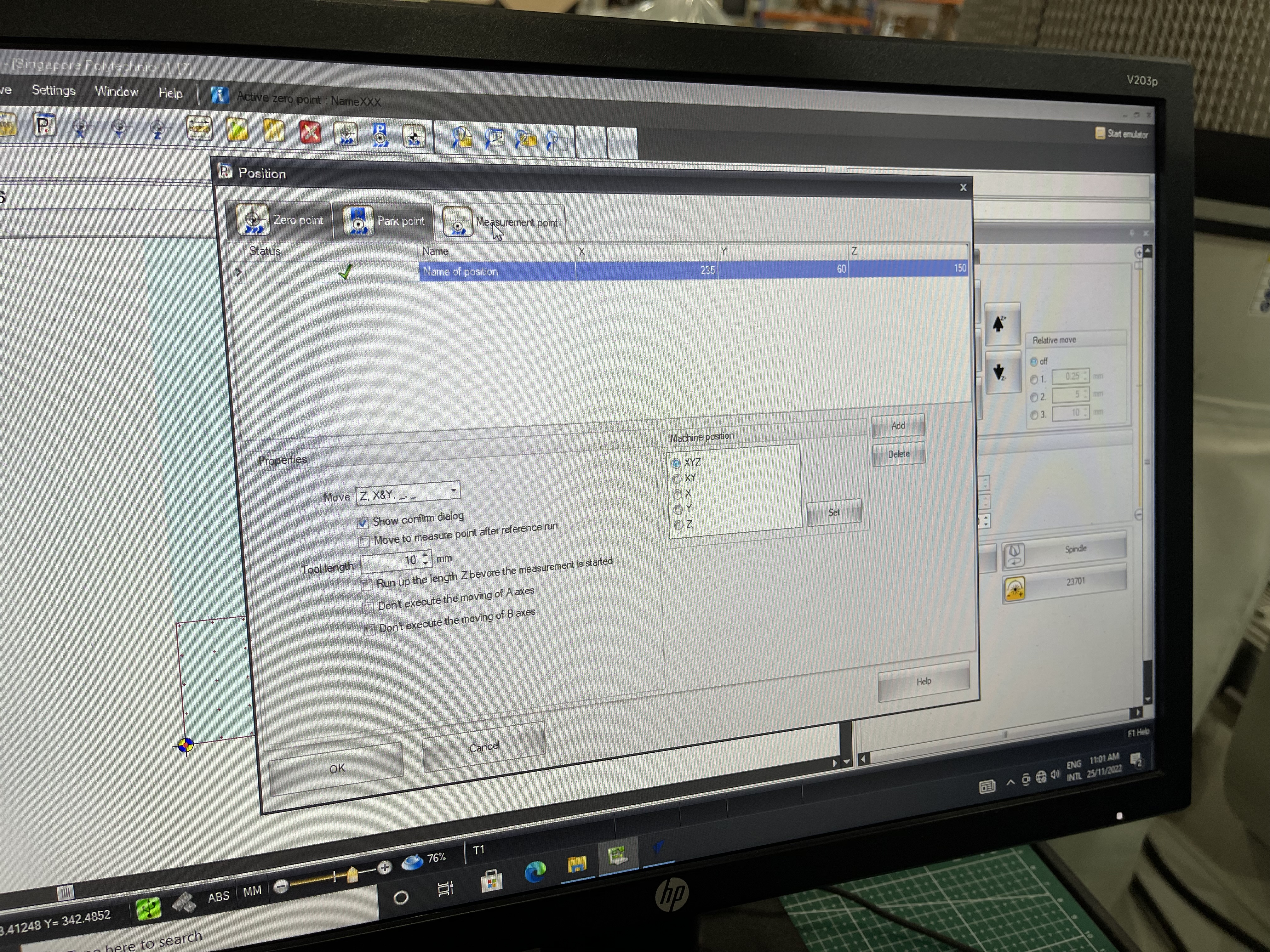
Step 3Once the G Code is exported, you can use NC viewer on the computer to open the file. With it you can set where the X and Y axis where the piece is going to be cut which will be your reference points. |
|
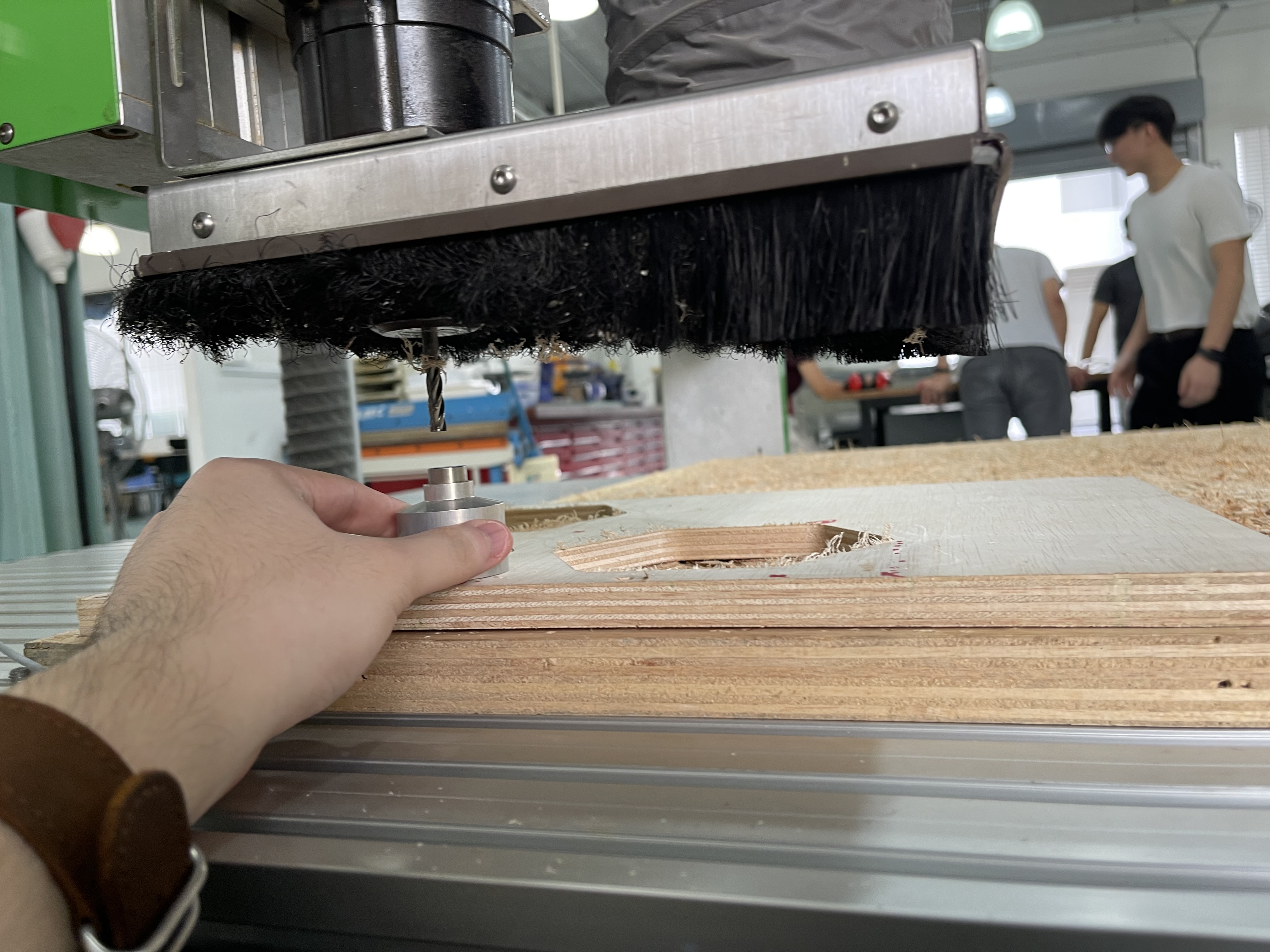
Step 4Before you cut ensure that the X, Y and Z reference points are set in the software. To set the Z coordinate of the router, use the Z axis limit switch to mark the Z axis refernce point. |
|
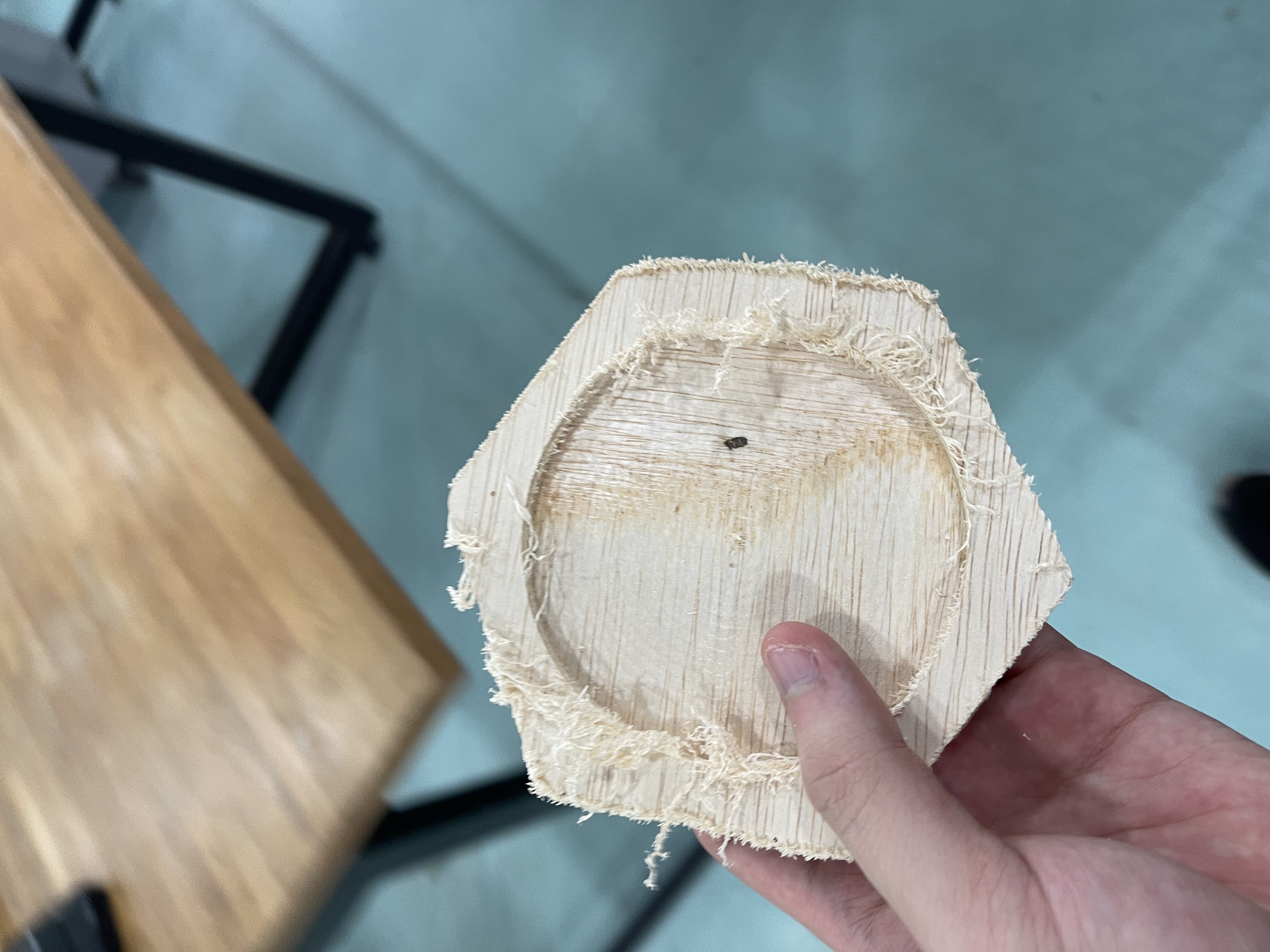
Step 5Once the router is done witth your workpiece, use a chisel to hammer out the tabs. |
|
Step 6With that, your workpiece is done. Make sure to sand the surface for a clean finish. |
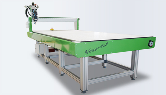
Final Project Fabrication: CNC Router Base Axis
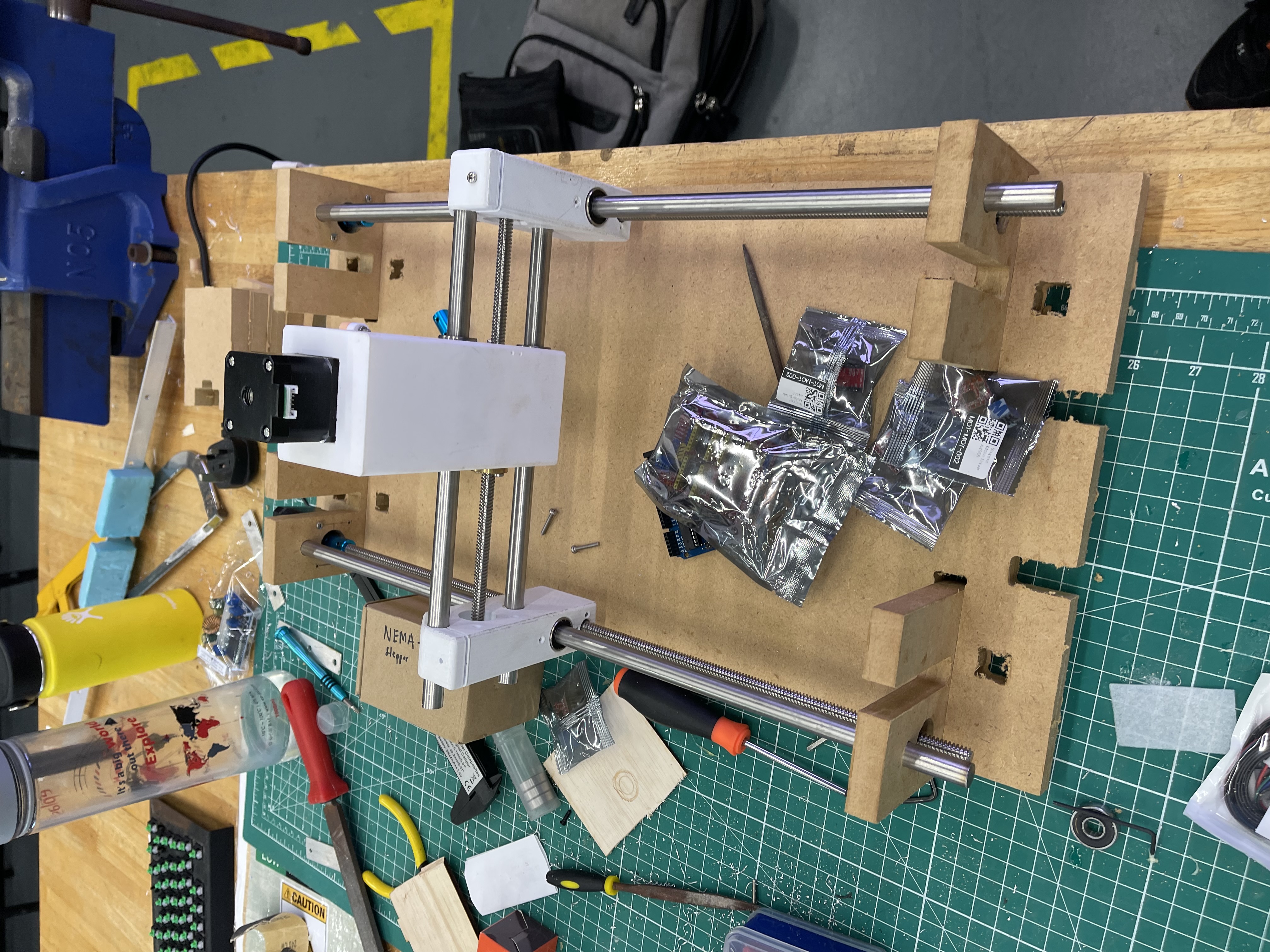
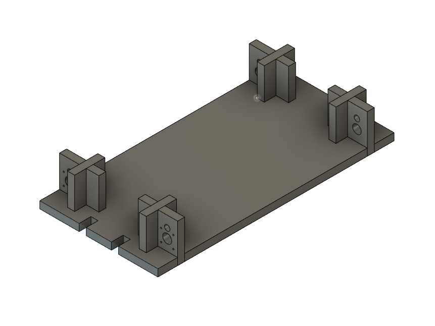
For my CNC assignement, I decided to CNC machine out the base for my CNC router that will be used for my final project.
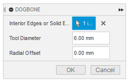
While making the base, I had to create a parameter for the thickness of the material as I do not know what lenght of thickness the Fablab had on at T11C. In additon to creating a variable parameter for the model, I had to also install a 'Dogbone' addon for Fusion 360. A dogbone is used when you want to joint two parts together using mortises and tenons. A cnc machine uses a round cutter and thus, can't make square holes. To get around this problem the 'Dogbone' is used to deform a sqaure to fit another sqaure in it. Shown in the picture below, the Dogbone addon has 3 parts to it. The top being a selector that allows you to choose which body the dogbone modification is applied to. The second is the tool diameter which is set to the tool diameter you will be using in the CNC router. The Radial Offset is used if the centre of the curve is accessible from the points on the tangent. However, this project will not need a radial offset.

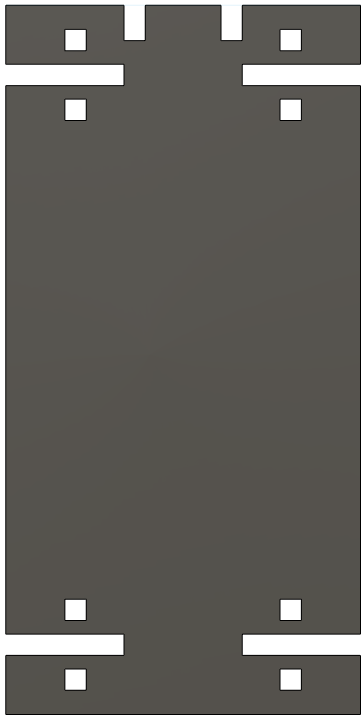
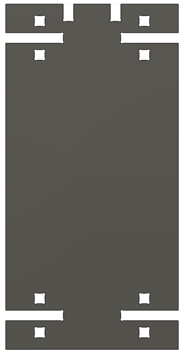
You can see a before and after picture at the bottom showing the differnce with dogbone and without dogbone. Notice how there are small curves in the corners of the base plate.
Lastly, the pieces are cut using Medium Density fibreboard. Which is a material that is harder than plywood. Therefore, I had to use a higher feedrate for the router so it can cut through the material more easily.
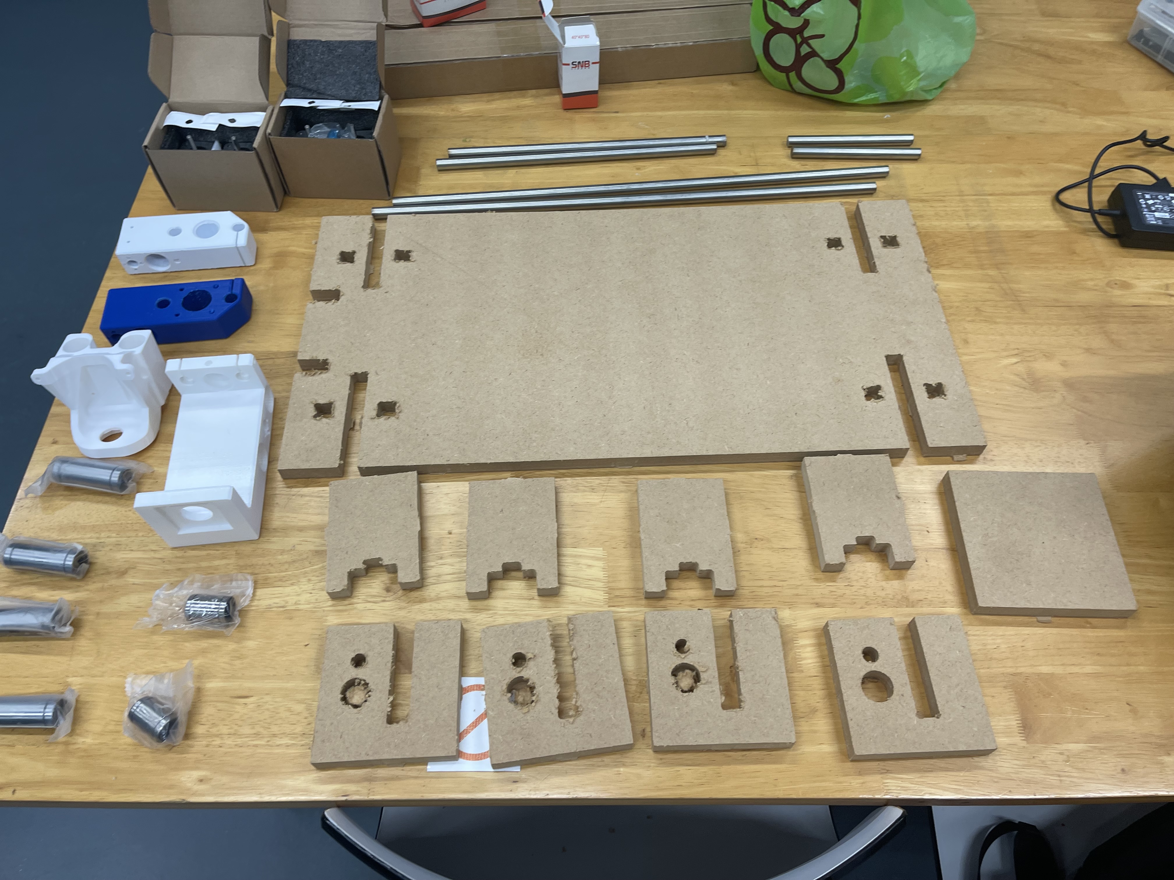
This is what the entire base looks like fully assembled.